American Concrete Institute Materials Journal

Analysis of Compressive Stress-Induced Cracks in Concrete
Kamran M. Nemati and Paulo J. M. Monteiro
Department of Civil and Environmental Engineering
University of California at Berkeley
Karen L. Scrivener
Department of Material Science
Imperial College of Science, Technology and Medicine
University of London, England, U.K.
Kamran M. Nemati ACI member, is a postdoctoral research fellow at the University of California at Berkeley. His research interests are in fracture mechanics of concrete, microstructural studies of concrete behavior under applied stresses, and experimental methods leading to preservation of cracks in concrete under load. He received his Ph.D. degree in civil engineering from the University of California at Berkeley. He is a registered professional civil engineer in California and several other states.
Paulo J. M. Monteiro ACI member, is Professor and Vice-Chair of Civil Engineering at the University of California at Berkeley, where he received his Ph.D. degree. His research interests include mathematical modeling and microstructure of concrete and testing methods. He held a Roy W. Carlson Distinguished Professorship at U.C. Berkeley during 1987-88; in 1989, Professor Monteiro received the Presidential Young Investigator award from the National Science Foundation.
Karen L. Scrivener took her first degree in Metallurgy and Materials Science at Cambridge University. In 1980 she went to Imperial College, where she studied the hydration of portland cement, pioneering the development of the use of backscattered electron imaging in the SEM for the study of cements and concrete. During her fifteen years at Imperial college she carried out research on many aspects of cement and concrete, including studies of cement clinker, slag, the paste aggregate interface in concrete, and durability problems. In 1995 she joined the Central Research Laboratories of Lafarge as Senior Scientist in charge of research on calcium aluminate cements.
Analysis of Compressive Stress-Induced Cracks in Concrete
Abstract
This paper presents the results of experimental studies of the micromechanical behavior of concrete under different loading conditions. Cylindrical specimens of normal and high-strength concrete were tested under uniaxial and confined compression. An alloy with a low melting point was used to impregnate the cracks and pores in the specimen. At the stress of interest, this alloy was solidified to preserve the stress-induced microcracks as they exist under load. Scanning electron microscopy (SEM) was employed to capture images from the cross sections of the concrete specimens. Stereological analysis that interprets three-dimensional structures by means of two-dimensional sections, was used on the computerized images to determine the density, orientation, and branching of the compressive stress-induced microcracks and the effect of confinement on microcrack behavior. The density and branching of the microcracks decreased as the confining stress increased. The confining stress had a pronounced influence on microcracks in the interfacial transition zone (ITZ) between the cement paste and aggregate. The amount of interfacial cracking decreased significantly as the confining stress was increased. Under uniaxial compression there were significant differences in the crack patterns observed in normal- and high-strength concretes. Under confined conditions the two types of concrete had similar microcrack patterns.
Keywords: concrete; microcracks; compressive stress-induced microcracks; scanning electron microscopy; Wood's metal, confinement; stereology; image analysis; interfacial transition zone; microcrack branching.
Research Significance
A special experimental technique has been developed to preserve compressive stress-induced microcracks in concrete as they exist under applied loads, subjected to various loading conditions. Several aspects of crack behavior under load as a function of confinement have been investigated.
Introduction
Concrete is a heterogeneous, multiphase material. On a macroscopic scale it is a mixture of cement paste and fine and coarse aggregates, with a range of sizes and shapes. On a microscopic scale the cement paste itself is found to be heterogeneous, consisting of unreacted cores of cement grains, crystalline and amorphous hydration products, and porosity.
With regard to its mechanical behavior, concrete is often considered to be a three-phase composite structure, consisting of aggregate particles dispersed in a matrix of cement paste and the transition zone which represents the interfacial region between the particles of coarse aggregate and the hydrated cement paste. The microstructure of cement paste in the vicinity of aggregate particles differs from that of the bulk paste. Many aspects of concrete behavior under stress can be explained by the characteristics and behavior of the cement paste-aggregate interfacial zone. This transition zone, typically 10 to 50
mm thick, is generally weaker than either of the two main components of concrete, and it therefore has a disproportionate influence on the mechanical behavior of concrete compared to its size.
Since the 1920s, researchers have suggested and assumed the existence of different kinds of defects called microcracks that occur in concrete [1,2,3,4,5]. However, only since the early 1960s have such cracks been observed, measured, and characterized in the interior of the system [6,7,8,9]. In the 1970s and 1980s the development of nonlinear fracture mechanics models enabled the structure and behavior of concrete to be taken into account. In the 1980s and 1990s, further research has led to the increasingly common application of fracture mechanics in the design of beams, anchorage, and large dams. In spite of this, the theory of fracture mechanics in concrete is not yet as mature as continuum theories, such as elasticity, viscoelasticity, and thermal problems. This is in part due to the limited understanding of the formation and propagation of microcracks in concrete.
Several methods have been used to study the microcracking of concrete. These include acoustic emission [2,3,10,11,12], sonic testing [13,14], microscope technique with dye [8,9], mercury intrusion porosimetry [15],
x-ray technique [16,17,18,19], optical and electron microscopy computerized tomography analysis [20], and holographic interferometry [21,22,23]. Some of these techniques are limited in their resolution, their sensitivity in detecting cracks, or their ability to make observations over a large area. Other methods are incapable of examining the specimen while under load or they require special preparation of the specimen, which alters its behavior. The method described here involves the application of a metal, Wood's metal, in the liquid phase, which preserves the microstructure under load of stress-induced microcracks in concrete.
Wood's metal has been used in the past few years to study the microstructure of different materials. Yadev [24] used Wood's metal to study the porosimetry and to measure contact areas and voids between the surfaces of natural fractures. Pyrak [25] used Wood's metal to study the fracture of rocks. Zheng [26] used Wood's metal to fill voids and microcracks in clastic rock specimens during loading and solidified it before unloading to preserve the microstructure in specimens under load.
Wood's metal, which has a melting point below the boiling point of water, is used in conjunction with scanning electron microscopy (SEM) and allows the detailed observation of microcracks in concrete as they exist under load. The concept of stereology, which deals with the interpretation of three-dimensional structures by means of their two-dimensional sections, can be applied to analyze the SEM images. Stroeven [27,28,29,30], Ringot [31], and Massat et al. [32] successfully applied the concept of stereology to study micromechanical aspects of concrete. With the advent of modern image analysis systems, it is now possible to perform stereological analysis on a great number of images accurately and expeditiously.
This investigation tested concrete cylinders of normal and of high-strength concrete in compression with various degrees of lateral confinement. While under load, the specimens were impregnated with Wood's metal to preserve the induced cracks. After the metal solidified, sections were cut from the specimens and examined in a scanning electron microscope. Image analysis and stereology were used to characterize the quantity and distribution of cracks. The objectives were to determine the shapes and geometry of stress-induced microcracks as they exist under load and to assess how the density, length, orientation, localization and behavior of microcracks depend upon the concrete type and confining stresses.
Experimental Technique
The test equipment created to preserve the cracks under applied load is described in detail elsewhere [33,34,35,36,37].
Five normal-strength and three high-strength concrete cylinders, 8 inches (203 mm) long by 4 inches (102 mm) in diameter, were cast with the mix designs shown in Table 1. The cylinders were cured for about one year in 100% humidity and a temperature of 23°
C.
Table 1: Concrete mix design
|
NORMAL-STRENGTH CONCRETE |
HIGH-STRENGTH CONCRETE |
|
MATERIAL |
QUANTITY/TYPE |
MATERIAL |
QUANTITY/TYPE |
|
Cement
Water
Coarse Aggregate
(1/2" Max. Size Aggr.)
Sand
High Range Water Reducing Admixture |
583 pcy (346 kg/m3)
308 pcy (183 kg/m3)
1,650 pcy (979 kg/m3)
1,448 pcy (859 kg/m3)
15 oz/100 # Cement Weight (10 ml/kg) |
Cement Type I/II
Rice Husk Ash
Crushed Limestone
(3/8" Max. Size Aggr.)
Top Sand (FM=3.0)
Water
Superplasticizer |
600 pcy (356 kg/m3)
90 pcy (53 kg/m3)
1,760 pcy (1,044 kg/m3)
1,325 pcy (768 kg/m3)
215 pcy (128 kg/m3)
5.7 Liters/m3 |
|
W/C: |
0.528 |
W/C |
0.358 |
|
Slump: |
1.5 inches (38 mm) |
Slump: |
1 inch (25 mm) |
|
Average Strength: |
6,200 psi (51.7 MPa) |
Average Strength: |
11,000 psi (75.8 MPa) |
The concrete cylinder ends were ground parallel to one another. Water was used as the cooling fluid during cutting and grinding. The confining stress used to generate triaxial compression was supplied by stainless steel wires, 0.041 inch (0.3 mm) in diameter, that were wound around the concrete cylinders at a pre-tension of 130 kN (150 lbf). In the partially confined case the wire was wound one third of the way from each end at a pitch of winding of 4 pitches per centimeter (10 pitches per inch) for Experiment #3, at a pitch of winding of 8 pitches per centimeter (20 pitches per inch) for Experiment #4, and along the entire length at a pitch of winding of 8 pitches per centimeter (20 pitches per inch) in the fully confined case.
Wood's metal (commercial name CerrosafeÒ
) is a fusible alloy. In the liquid phase it is nonwetting, with an effective surface tension of about 400 mN/m [24]. It consists of 42.5% bismuth (Bi), 37.7% lead (Pb), 11.3% tin (Sn), and 8.5% cadmium (Cd). It has a melting range from 160°
F to 190°
F (71.1°
C to 87.8°
C) and is solid at room temperature. Wood's metal has a Young's modulus of 9.7 GPa, a density of 9.4 g/cm3, and does not go through any volume change during hardening. The advantage of such an alloy is that it can be intruded into voids and stress-induced microcracks while the specimen is held at the desired stress level and then solidified to preserve the geometry of the microcracks induced. The concrete cylinders were first dried in an oven at a temperature of 110°
F (43.3�C). This removed the moisture in the concrete and preheated the cylinder, ensuring that the molten metal alloy could penetrate into pores and cracks deep within its core without solidifying prematurely.
A total of eight experiments, five of normal-strength and three of high-strength concrete cylinders, were conducted with conditions as defined in Table 2. Each specimen was loaded to a similar point in the stress-strain curve, corresponding to about 80-85% of the ultimate strength.
Table 2: Experiments conducted
|
Expt.# |
Loading
Condition |
Concrete
Strength |
Load (psi/MPa) |
% Ultimate Load |
|
1 |
No Load |
Normal |
1,500/10.3* |
N/A |
|
2 |
Uniaxial |
" |
5,000/34.5 |
80 |
|
3 |
Partially Confined 1 � |
" |
6,000/41.4 |
81 |
|
4 |
Partially Confined 2 � |
" |
6,000/41.4 |
82 |
|
5 |
Fully Confined |
" |
7,330/50.6 |
84 |
|
6 |
No Load |
High |
1,500/10.3* |
N/A |
|
7 |
Uniaxial |
" |
9,350/64.5 |
85 |
|
8 |
Partially Confined |
" |
10,800/74.5 |
82 |
*restraining load to prevent movement of the specimen during impregnation.
�pitch detail: Pitch of winding of 4 pitches per centimeter (10 pitches per inch)
�pitch detail: Pitch of winding of 8 pitches per centimeter (20 pitches per inch)
After solidification of the metal each of the cylinders was sectioned along its long axis, using oil as a coolant. One of the half-cylinders was sectioned at the middle along its diameter. An axial slab, approximately 1/8-inch thick, was sliced parallel to the direction of the load. Four sections were extracted from the axial slab (specimens 1-4), two from the mid-line edge, and two from the top surface. In the micrographs each section is identified by a two digit code, the first referring to the experiment number (Table 2) and the second to the section number (Figure 1). The sections were 1-inch (25 mm) square and had an approximate thickness of 5 mm.
One side of each section was lapped flat with 120#, 220#, 320#, and 600# silicon carbide using a rotating grinder and then mounted against a 1-inch (25 mm) diameter glass plate with epoxy. A parallel-sided slice, 2-3 mm thick, was then cut from the section with a diamond slicing wheel and a nonaqueous lubricant (Propylene glycol coolant). The sections were lapped with a wheel grinder and polished with 600# silicon carbide, 100-, 50-, and 10-micron aluminum powder and 5-, 3-, and 1/4-micron diamond paste. After each stage of polishing, the specimens were immersed in acetone and placed in an ultrasonic bath.
Figure 1: Specimen extraction and numbering scheme
The specimens were examined at the Materials Department of the Imperial College of Science and Technology and Medicine, London, using a JEOL JSM-35CF scanning electron microscopy (SEM) in conjunction with a KONTRON SEM-IPS image analyzer.
Stereological Relationships
Stereology deals with the interpretation of three-dimensional structures by means of their two-dimensional sections. There are various approaches to stereological problems. The statistico-geometrical approach depends on measuring and classifying a large number of two-dimensional images and is the method utilized in this study. It is applicable when objects are randomly distributed in space. In such cases valid results may be obtained from a single section, if this is extensive enough to contain a statistically significant number of features and is representative of the bulk specimen.
Fundamental expressions have been determined which relate measurements on two-dimensional sections to the three-dimensional structure. Table 3 presents some of the symbols commonly used relevant to this work.
Table 3: List of basic stereological symbols and their definition
|
Symbol |
Dimensions |
Definition |
|

|
m
m-1 |
Number of intersections per unit length of features (i.e., cracks) in a section with a superimposed array of equally spaced, randomly oriented parallel lines. |
|

|
m
m-1 |
Number of intersection of cracks in a section with an array of equally spaced parallel lines oriented at an angle q
to a reference axis. |
|

|
m
m/m
m2 |
Total crack length in a section per unit of area |
|

|
m
m2/m
m3 |
Total crack surface area per unit of volume |
The relationships between and with are presented below [38].
Surface area per unit volume, :
 (1)
(1)
Length of line per unit area, :
 (2)
(2)
or
 (3)
(3)
Image Analysis Procedure
The samples were examined in the scanning electron microscope with backscattered electrons (BSE). The SEM was operated at 15 kv and probe current of around 1 nA at a working distance of 15 mm. The images were acquired by the image analyzer at a magnification of ´
60 and digitized into an array of 512 ´
512 pixels, with 256 gray levels (1 pixel = 3.3 �m); 55 images were extracted from each sample. A typical gray level BSE image is shown in Figure 2.
|

|
|
|
Figure 2: A typical BSE image |
Figure 3: Establishing threshold in histogram |
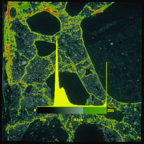
Figure 3 shows a histogram of the distribution of gray levels in the BSE image superimposed on the original image. As the average atomic number of the Wood's metal is much higher than cement paste and the aggregates, impregnated cracks and pores can be easily distinguished in the BSE image. This technique also avoids the problem of crack formation during specimen preparation. The peak at the right (high gray level) corresponds to the areas of Wood's metal, while the peaks to the left correspond to the cementitious phases and aggregate. This histogram was used to select the threshold value for discriminating the areas of Wood's metal, shown in Figure 4.
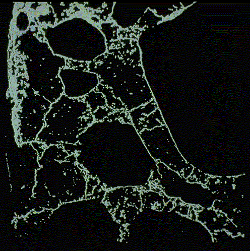
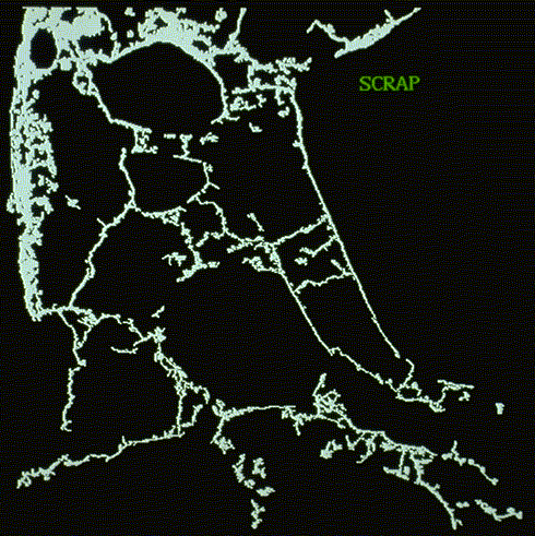
The image shown in Figure 5 includes small isolated pores, which were eliminated by the application of a minimum size threshold (scrap) for objects of 10 pixels (minimum feature size of approximately 33 �m).
|
|
|
|
Figure 4: Thresholded image |
Figure 5: Crack network image after application of scrap function |
Next, a skeletonized binary image was obtained by binary thinning (thinbin function). For every thinning step, pixels that are not relevant to the connectivity of an object are removed from the object margins, i.e., converted into background pixels, thus connectivity of objects is maintained. This process was continued until all objects were reduced to a width of one pixel that approximates the skeleton. Figure 6 is the final binary image used for stereological measurements.
|

|
|
Figure 6: Binary-thinned image of the crack network in concrete |
To quantify the crack orientation, the skeletonized image in Figure 6 was then intersected by an array of straight parallel lines at 15°
angular increments, in this case at angles of 0°
, 15°
, 30°
, 45°
, 60°
, 75°
, 90°
, 105°
, 120°
, 135°
, 150°
, and 165°
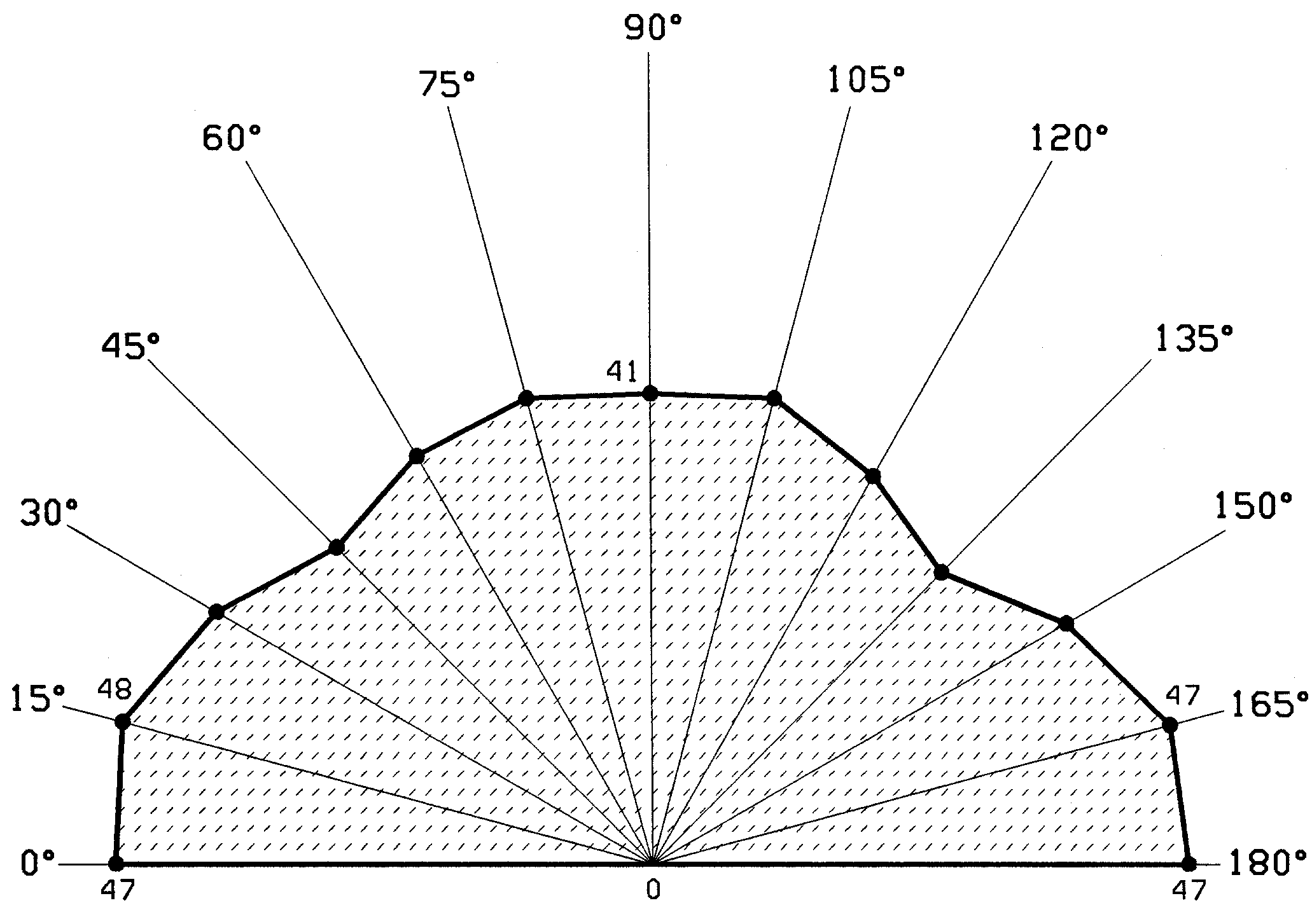
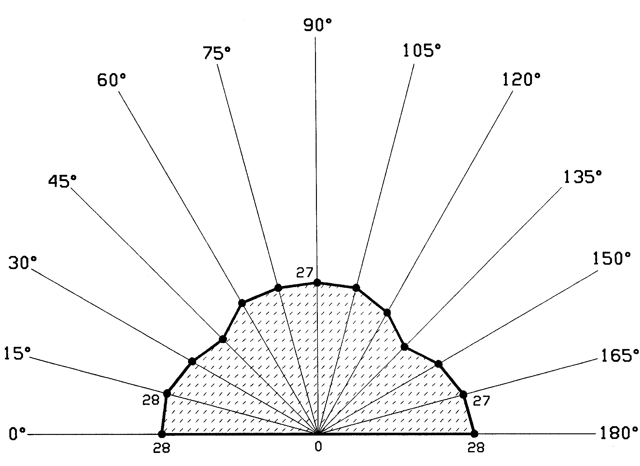
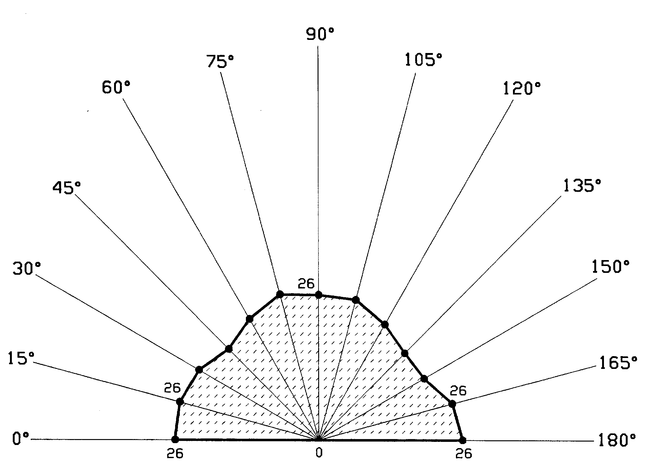
to the compression axis (Figure 7). At each angle the number of intersections of the line array with the thinned crack network was measured. A vector of length proportional to the number of intersections, , was plotted at the q
to give a rose of intersections diagram, which characterizes the anisotropy of the cracks. Since lines at angle q
+180� are equivalent to those at angle q
, the rose diagrams only cover the range of 0°
to 165.
Figure 7:
Array of straight parallel lines at 15°
angular increments
This method allows the anisotropy of the crack pattern to be characterized. For example, if most cracks were oriented parallel to the compression axis the number of intersections with the lines at 90°
would be highest. Further image analysis procedures are discussed in the next section.
RESULTS
Characterization of Microcracks
Normal-Strength Concrete
Figure 9 shows typical images from the unloaded specimen.
Figure 9:
SEM micrographs from the no-load experiment
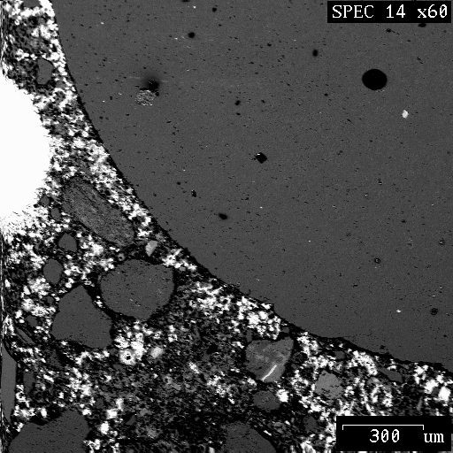
In order to restrain the specimen during the impregnation with Wood's metal this specimen was subject to a small uniaxial compressive stress of 1,500 psi (10.3 MPa.) In this specimen the bright areas that have been permeated by Wood's metal correspond to regions of connected porosity. These regions are most common in the interfacial transition zone around aggregate particles, a finding which is discussed in more detail elsewhere [37]. The connectivity (and hence degree of penetration by Wood's metal) of these pore agglomerations could have been enhanced by the formation of bridging microcracks during the curing of the samples and the drying process prior to loading. There are no long cracks characteristic of stress induced cracking in these images. In contrast such cracks are readily apparent in the samples from the loaded unconfined specimen, shown in Figure 10.

Figure 10: SEM micrograph from the uniaxial experiment
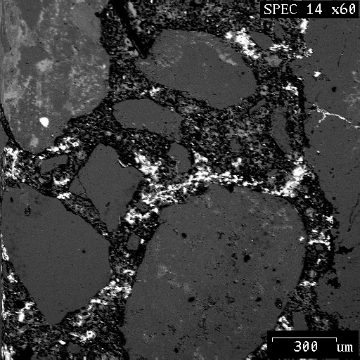
The microcracks in the loaded specimens appear to have been generated by several different mechanisms. Figure 11 shows two micrographs taken from the partially confined sample (Experiment #3). Microcracks have propagated through the cement paste and along the transition zone. Many cracks appear to have been generated from voids as a result of local tensile stress tangential to the void boundary, with a value of the order of the maximum applied principal stress. These cracks usually originated from the pore boundaries and propagated in the direction of maximum compression. Figure 12 shows two micrographs of microcracking around air voids, which are filled with Wood's metal.
Figure 11:
SEM micrographs from the partially confined experiment
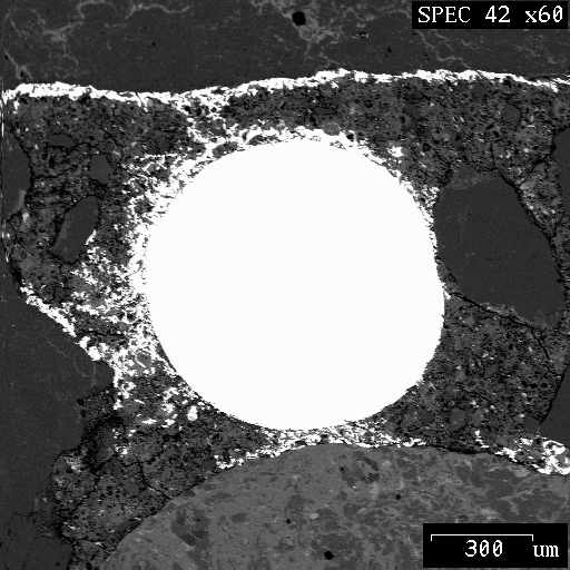
Figure 12:
SEM micrographs of microcracks propagating from a pore
Microcracks also appeared to have been generated inside aggregates, with a tendency to run parallel to the compression axis. It is presumed that these aggregates experienced loading across their height leading to a mode of fracture analogous to that which occurs in a splitting tensile test. Figure 13 shows two micrographs of this phenomenon for two different loading conditions- fully confined and partially confined.
Figure 13:
SEM micrographs of aggregate cracking
High-Strength Concrete
High-strength concrete behaves more like a homogeneous material than does normal-strength concrete. The stress-strain curves for high-strength concretes are steeper and remain closer to linearity to a higher stress-strength ratio than in normal- strength concretes. In addition, fracture in high-strength concrete tends to be characterized better by linear elastic fracture mechanics than does normal-strength concrete []. This has been attributed to a decrease in the amount and extent of microcracking in the interfacial transition zone (ITZ) between the cement paste matrix and the aggregates. Thus, high-strength concrete exhibits a more brittle mode of fracture and less volumetric dilation []. High-strength concrete has a stronger cement paste due to a lower water/cement ratio, which results in a closer packing of cement grains and a reduced amount of pores and cracks. Apart from this microstructurally improved matrix, high-strength concrete also has a stronger transition zone. This presumably results from the reduction of excess bleeding and the filling of gaps by mineral admixtures, which in this case was rice husk ash.
Figure 14 shows two SEM micrographs from the unloaded specimen of high-strength concrete. No stress-induced microcracks were observed in these sections. Regions of connected porosity in the ITZ are also far less apparent, which is due to the refinement of the microstructure in this region.
Figure 14:
Micrographs of high-strength concrete
Figure 15 shows two SEM micrographs from Experiment #7, which was conducted under uniaxial condition. From these micrographs it is clear that less cracking occurs in high-strength than in normal-strength concrete; because of the stronger cement paste, most of this cracking takes place in the transition zone.
Figure 15
Micrographs of high-strength concrete
Microcrack Density Distribution
Plots of the cracks surface area per unit volume,  , as a function of confinement are presented in Figure 16 for normal-strength and high-strength concrete specimens. The value of was obtained based on the average value of in all directions. It is clear that the crack surface area, , decreases as the confining stress increases for both normal and high-strength concrete.
Figure 16: Crack surface area () as a function of confinement for normal and high-strength concrete
As illustrated in Figure 9, in the unloaded normal-strength sample the Wood's metal penetrates into connected pores, which are then measured as 'cracks' by the image analysis program. The samples from the unconfined experiment (#2) show a considerable increase in over the unloaded samples. In all the normal-strength confined specimens (Experiments #3-5) the measured is actually lower than that in the unloaded sample. This may be attributed to the decrease in the amount of connected porosity penetrated by the Wood's metal, either due to the closure of bridging microcracks or to the collapse of pore throats under the confining pressure.
In the high-strength concretes, in the unloaded sample was lower than in the case of the normal-strength concrete. This is due to the decrease in the amount of connected porosity in the ITZ as noted from the micrographs (Figure 15). There is a dramatic increase in the crack density in the unconfined sample, but again the crack density in the confined sample is much lower. In both uniaxial and confined cases the crack densities in the normal- and high-strength concrete are similar. Although the absolute loads were different, the testing conditions correspond to similar percentage of the ultimate load.
Kranz [] put forward an explanation for the decrease in crack density in the presence of confinement. Microcracks are generated by local tensile stresses, which depend on the geometry of pores and aggregates, and material heterogeneity, as well as the magnitude and direction of applied stresses. Confinement increases the hydrostatic pressure acting on an existing deviatoric stress field, and so is likely to decrease the range and magnitude of deviatoric stresses concentrated near crack tips, as well as increase frictional resistance to shear between crack surfaces in contact. For tensile cracks this increases the energy (and hence stress) required for propagation, thereby making crack growth less probable.
The microcrack density distribution, G
, represents the number of microcracks per unit of observation area. Pore spaces were not counted as microcracks. For a body of volume  (unit thickness) containing
  cracks with initial cracks of length
  , the initial crack density parameter G
is given by:
, the initial crack density parameter G
is given by:
 (4)
(4)
The crack density parameter G
, in an image of area  with cracks of length
  , can be obtained from the following relationship:
 (5)
(5)
Where:
G
= Crack density parameter
= Crack length (mm)
= sem image area (512 pixels ´
512 pixels = 2.8358 mm2)
Figure 17 illustrates the crack length and crack densities for the partially confined specimens in both confined and unconfined portions of the specimen for Experiments #3 and #4 which were subjected to a confining stress over each end and uniaxial compression over the center. In both cases the crack densities in the center and edge of the sample are smaller in the confined portion than in unconfined portion. Also, in both experiments, the average crack length is smaller in the center portion of the specimen than along the edge.
Figure 17: Diagrammatic representation of crack length and crack density at confined and unconfined portions
Orientation of Microcracks
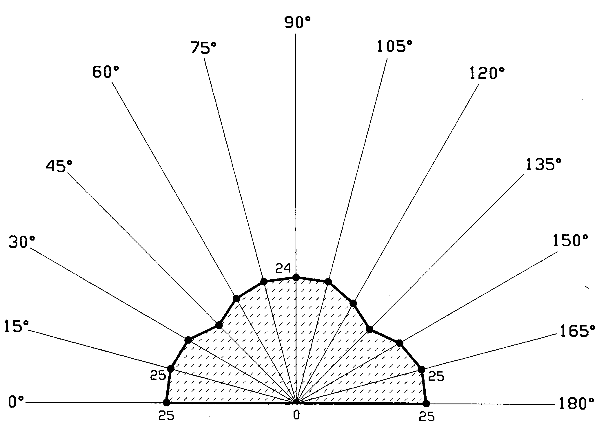
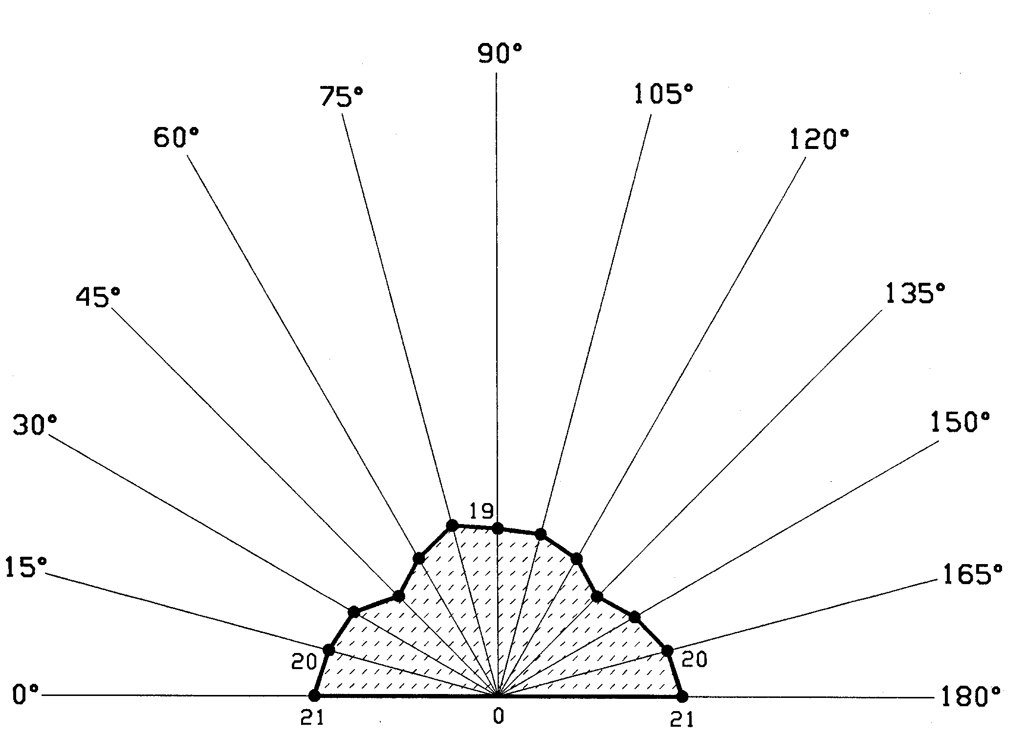
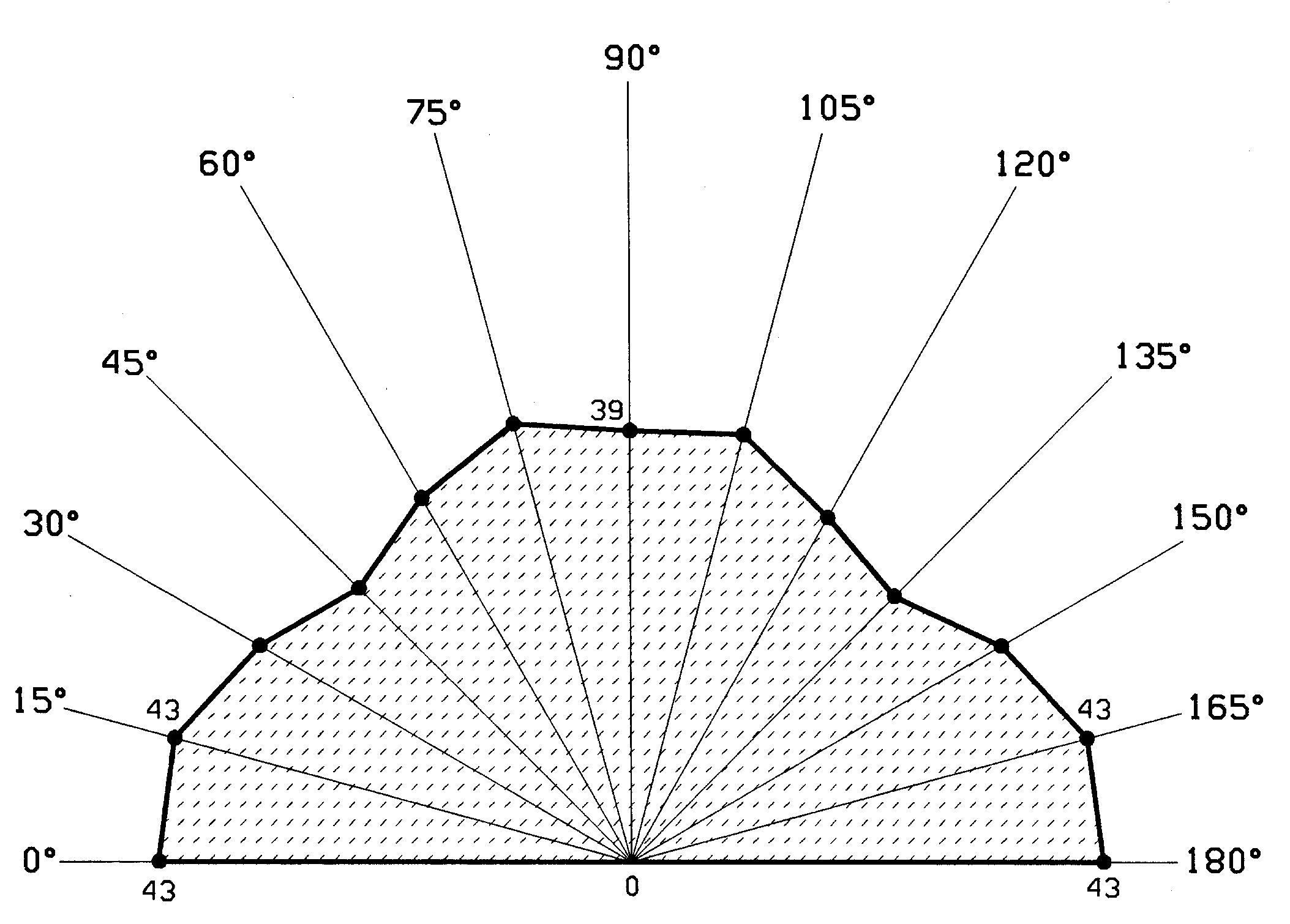
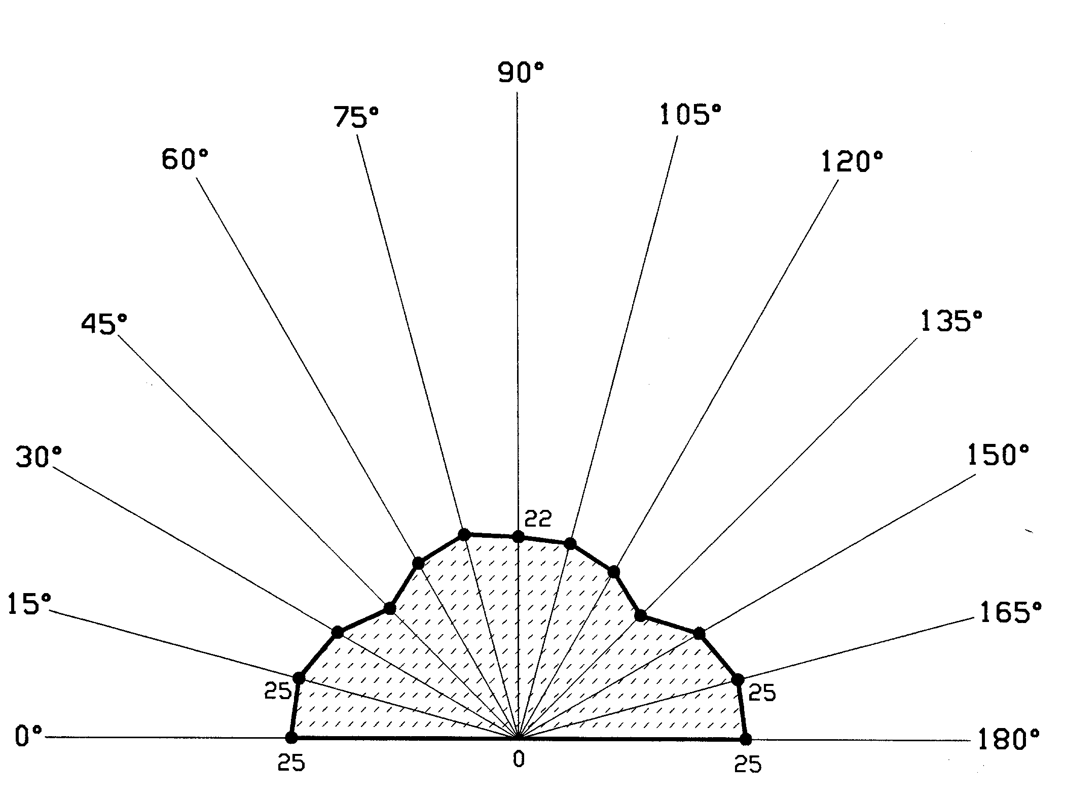
Figure 18 shows the rose of the number of intersections for normal and high-strength concrete specimens. The degree of orientation obtained for the partially confined specimens were based on the crack patterns observed in the confined portion.
From Figure 18 it is apparent that on a microscopic scale, the cracking is relatively isotropic. The normal-strength uniaxial section shows some tendency for a higher number of intercepts for line arrays oriented parallel to the stress axis, indicating that the cracks in this section tended to run perpendicular to the loading direction. However, this tendency is not present in the normal strength confined sections. The high-strength concretes show a very slight, probably insignificant, orientation effect in both the uniaxial and confined specimens.
Any tendency to anisotropy of cracking, which might have occurred in a homogeneous material, will be greatly affected by the heterogeneity of concrete. In particular, visual examination makes it clear that a large proportion of the cracks occur at the cement paste /aggregate interfaces, which will be randomly oriented.
|

Exp.1 |
Exp.2 |
|
Exp. 3 |
Exp. 4 |
|
Exp. 5 |
Exp. 6 |
|
Exp. 7 |
Exp. 8 |
Figure 18:
Rose of the number of intersections diagrams for normal- and high-strength concrete (results of partially confined 1 and 2 conditions are from the confined portion of the specimen)
Interfacial Cracks and Pores
Qualitative examination of the sections indicate that the cracking was dominated by cracks at the interface between aggregate and cement paste and by the presence of regions of connected pores in the ITZ.
Investigations have shown that very fine cracks at the interface between coarse aggregate and cement paste exist even prior to application of the load on concrete [8]. The initiation and propagation of these cracks are considered to be the dominant mechanisms responsible for the nonlinear response of concrete subjected to uniaxial compressive loading. Interfacial cracks remain stable up to about 30 percent or more of the ultimate strength and then begin to increase in length, width, and number. The overall stress under which they develop is sensitive to the water/cement ratio of the paste. At 70 to 90 percent of the ultimate strength, cracks open through the cement paste and bridge the interfacial cracks, and the continuous crack pattern is formed []. Studies conducted using microscopic analysis [8,,] reveal that cracks frequently initiate at the interface and then propagate into the matrix where mortar cracks join to form a continuous crack path prior to ultimate load.
In order to analyze the phenomenon of interfacial pores and cracking, an attempt was made to distinguish these from the matrix cracks. The outline of the aggregate particles in the image was identified by manual tracing. The areas corresponding to the aggregate particles were then dilated by about 13 �m and cracks within this dilated region identified. The length of these interfacial cracks was then calculated as a percentage of the total crack length in the image. Figure 19 shows the percentage of interfacial microcracks and pores as a function of the confining stress for normal and high-strength concrete. As shown, there is a sharp reduction in the amount of interfacial microcracks as the confining stress increases. The greatest reduction occurred when the concrete specimen was fully confined.
Figure 19: Effect of confinement on interfacial microcracks of normal and high-strength concrete
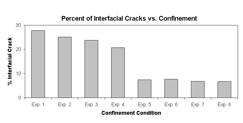 In the case of high-strength concrete, it is apparent that the percentage of interfacial cracks in the unloaded and uniaxially loaded specimens is much lower than in the corresponding of normal strength concrete specimens. This may be partially explained by the elimination of the region of connected pores which were a common feature of the ITZs of the normal-strength concrete, but also confirms the improvement of the strength of the interfacial zone in the high-strength concrete. In the confined case the percentage of interfacial cracks is similar in the two types of concrete.
Microcrack Branching
Cracks with frequent branching are often observed in the fracture of brittle and quasi-brittle materials, such as ceramics and concrete. The crack-branching patterns of materials are very complex and irregular; however, quantitative analysis of branching patterns could reveal some important information about the stress applied during crack propagation, as well as material characteristics, such as surface energy and the elastic constant [,]. Fractal analysis has also been applied to complex branching patterns [40,41,].
Since the images being analyzed are a general indication of the crack pattern, they can be considered to be a very broad estimate of crack complexity. Therefore the crack branching analysis presented here should be considered as a comparative measure between the samples. For this purpose a computer program was developed to measure the number of 3-way and 4-way crack-branching nodes which appeared in the skeletonized images, similar to the ones shown in Figure 20.
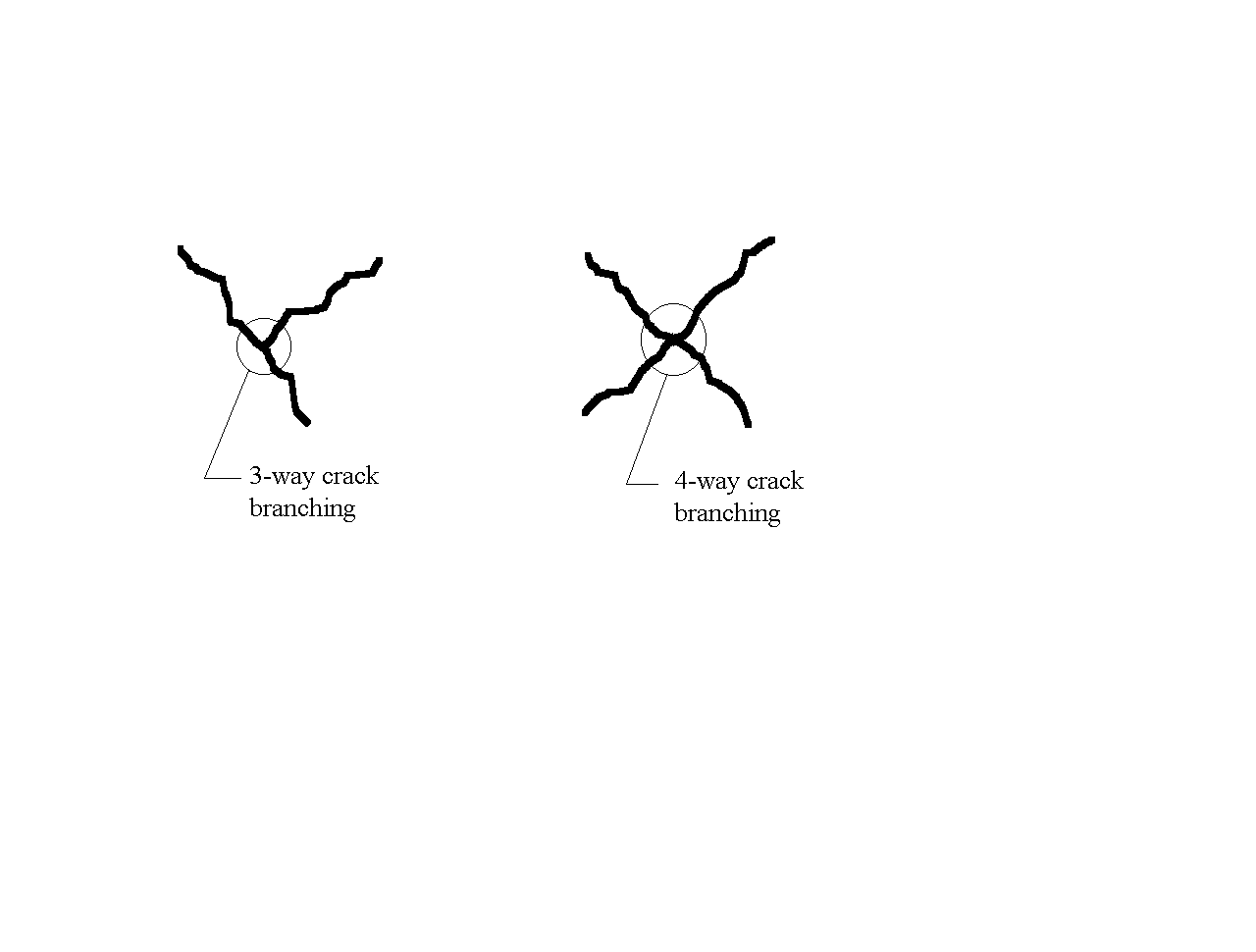
Figure 20: 3-way and 4-way crack-branching nodes
In order to normalize the number of crack-branching nodes, the number was divided by the crack surface area per unit volume, . Figure 21 shows that as the confining stress increases, the number of crack-branching nodes decreases. This is expected since the propagation of microcracks is controlled by the stress intensity factor at the microcrack tips; as the confining stress increases, the negative stress intensity factor imposed by confinement increases proportionately. This increases the energy required for cracks to grow and branch off. The amount of branching in the high-strength concrete is slightly less than the number of cracks in the normal-strength concrete for the uniaxial loading condition, but similar in the confined case. This can be attributed to the fact that high-strength concrete is more brittle than normal-strength concrete. As a result, when fracture occurs in high-strength concrete, the crack propagation is associated with less branching.
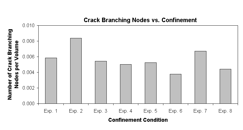 Figure 21: Crack-branching nodes as a function of confinement for normal and high-strength concrete
Summary and Conclusion
This paper reports on an experimental technique that has been developed to preserve the stress-induced microcracks as they exist under compressive load, by the intrusion and solidification of Wood's metal. This technique was applied to study the behavior of both normal- and high-strength concrete in uniaxial and confined conditions.
By analysis of BSE images and the application of stereology, various measures of the crack density and distribution were obtained: crack surface area per unit volume; crack orientation; average crack length; and crack branching.
In the unloaded normal-strength concrete most of the areas intruded by the Wood's metal were interconnected pores in the interfacial transition zones (ITZs) around aggregate particles. These areas were less apparent in the high-strength concrete, confirming the improved microstructure of the ITZ in these concretes.
The measured surface area of cracks increased considerably when the specimens were loaded uniaxially. At similar percentages of the ultimate loads the crack density in the normal and high-strength concrete were similar.
Confinement dramatically decreased the crack density observed in the loaded samples. In the normal-strength concretes the crack density was lower than in the unloaded samples, as it was more difficult for the Wood's metal to intrude through the ITZs.
Measurements of the orientation indicated that the cracks were relatively isotropic at a microscopic level. This may be partly due to the domination of interfacial cracks, which must be randomly oriented.
In the unloaded and uniaxially loaded specimens the percentage of interfacial cracks was much higher in the normal-strength than in the high-strength concrete. Confinement decreased the percentage of interfacial cracks to a similar level for both types of concrete.
For uniaxial loading the cracks were less branched in the high-strength concrete. Confinement reduced the level of crack branching per unit length of crack for both types of concrete.
The crack densities in the center and edge were smaller in the confined portion than in unconfined portion. In the same specimens the average crack length was smaller in the center portion of the specimen than along the edge.
One disadvantage to using the Wood's metal method is that the concrete cylinders are dried prior to testing. They are pre-heated at a temperature of about 43°
C to remove the moisture in the concrete and to ensure that the molten metal alloy can penetrate into the pores and cracks deep within the core without solidifying prematurely. This process could induce excessive drying, thereby shrinkage cracks which may percolate through the sample.
Acknowledgment
The authors would like to express their appreciation to Professor Neville G. W. Cook and Dr. Larry R. Myer of the University of California at Berkeley for their guidance in designing the test apparatus and for advice on experimental procedures. Special thanks goes to Mr. William MacCracken of the Department of Civil Engineering for his insight and ingenuity in conducting the experiments, and to Mr. Stephen Laing of the Department of Material Science at the Imperial College in London for his help in computer programming. The study reported here was funded through the grant MSM-8957183 from the National Science Foundation.
References