Published in: Cement and Concrete Research, Volume 27, Number 9, pp. 1333-1341, September 1997.

A New Method to Observe Three-Dimensional Fractures in Concrete Using
Liquid Metal Porosimetry Technique
Kamran M. Nemati and Paulo J. M. Monteiro
Department of Civil and Environmental Engineering
University of California at Berkeley
Berkeley, California 94720, U.S.A.

Abstract
The technique described here makes it possible to observe microcracks in concrete in three-dimensions with apertures as small as 0.1
mm. An alloy with a low melting point was used to penetrate cracks and pores in cylindrical specimens of normal and high-strength concrete subjected to uniaxial and confined compressive stresses. After the induction of fractures, an alloy was solidified to preserve the shapes of stress-induced microfractures as they exist under load. After the alloy was solidified, the surface of the specimens were etched with 1 molar hydrochloric acid, leaving a skeleton of alloy network on top of the new surface. Micrographs using a Scanning Electron Microscope (SEM) revealed a complex three-dimensional network of metal-filled fractures and voids.
Introduction
Concrete is a heterogeneous material consisting of three components: bulk cement paste, aggregates, and interfacial transition zone (ITZ) (which is a thin shell with a thickness of 10 to 50 m
m). The ITZ is considered to be weaker than either cement paste or aggregate; its microstructure is distinctly different from that of bulk cement paste in that its highly porous owing to higher water/cement ratio caused by the wall effect of the aggregate particles. Hence, ITZ has a profound influence on the mechanical behavior concrete.
Many researchers have tried to preserve, characterize, and study the fracture of concrete under sustained loads (1-7). Among the latest developments in preserving fractures in concrete (8,9) and rocks (10) as they exist under applied stresses is the use of a molten metal alloy, known as Wood's metal which has a melting point ranging from 71°
C to 88°
C. The advantage of such an alloy is that it can be intruded into voids and stress-induced microcracks while the specimen is held under applied loads and then solidified to preserve the geometry of the induced microcracks. The concrete specimens can then be submerged in 1 Molar hydrochloric acid (HCl) in order to dissolve the cementitious portion of the specimen, leaving a Wood's metal cast of the stress-induced fractures and void structure. The advantage of such a technique is that it is not necessary to cut thin sections of the specimens to observe the fracture network. By continuously etching the concrete matrix down to a depth corresponding to microscope's depth of field, it makes it possible to observe the three-dimensional fracture network of the whole specimen.
Experimental Technique
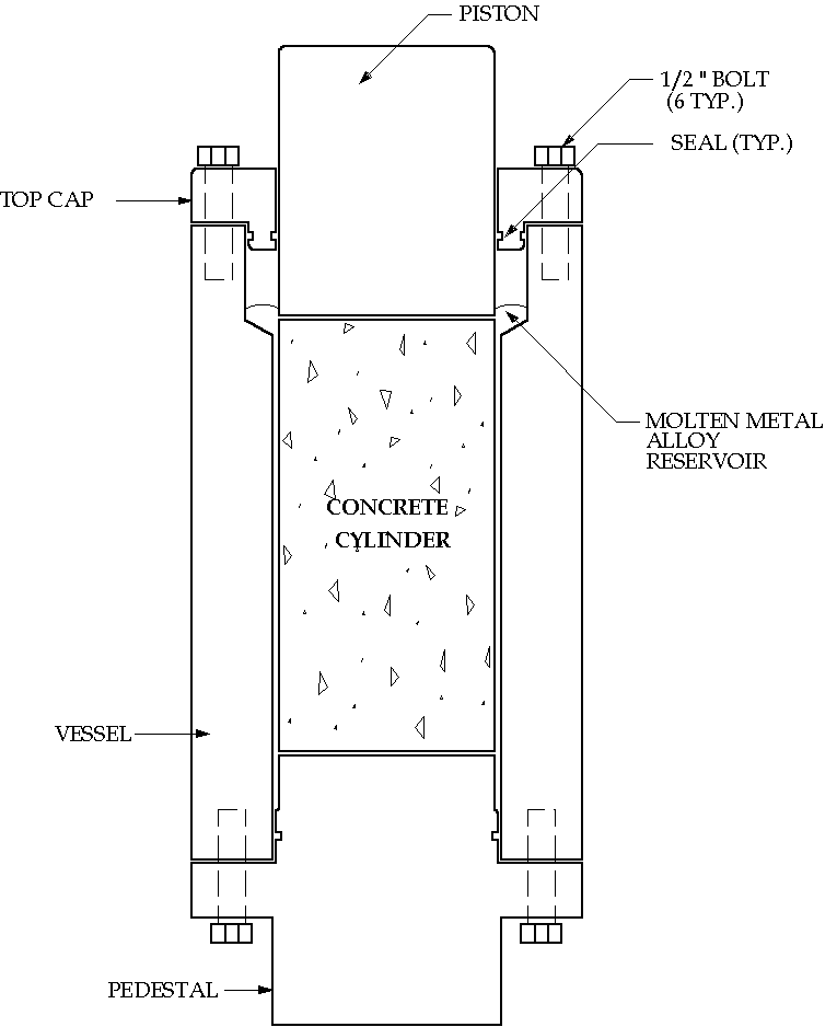
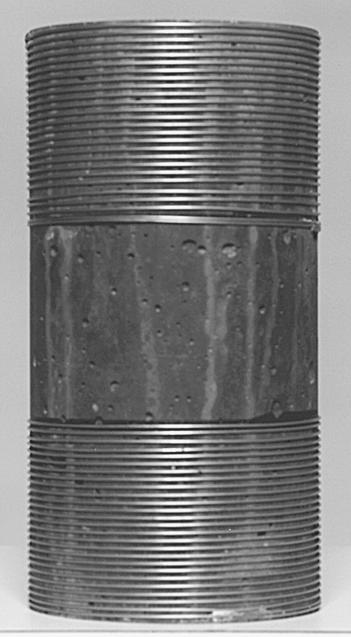
The test equipment created to preserve the cracks under applied load is described in detail elsewhere (8,9) and is schematically shown in Figure 1(a). The concrete samples used for this experiment were normal and high-strength concrete cylinders, with the dimensions of 203 mm (8 inches) long by 102 mm (4 inches) in diameter which were tested in compression with various degrees of lateral confinement. The ultimate strengths for the normal and high-strength samples were 52 MPa (7,500 psi) and 76 MPa (11,000 psi), respectively. While under load, the specimens were impregnated with Wood's metal to preserve the induced cracks. Wood's metal is a fusible alloy which is nonwetting in the liquid phase, with an effective surface tension of about 400 mN/m, a Young's modulus of 9.7 GPa, and a density of 9.4 g/cm3. It consists of 42.5% bismuth, 37.7% lead, 11.3% tin, and 8.5% cadmium. In order to saturate the induced microcracks with the molten metal, nitrogen pressure at 10.3 MPa (1500 psi) was applied to the molten metal as the pore pressure, which was kept constant throughout the tests and which did not alter the effective stresses on the concrete cylinder. With a surface tension of 400 mN/m, the alloy penetrated into flat cracks with apertures as fine as 0.08 microns. The confining stress used to generate triaxial compression was supplied by stainless steel wires, 0.3 mm (0.041 inch) in diameter that were wound around the concrete cylinders at a pre-tension of 130 kN (150 pounds), as shown in Figure 1(b). Each specimen was loaded to a similar point in the stress-strain curve, corresponding to about 80-85% of the ultimate strength.
After such induction and preservation of stress-induced fractures in concrete using Wood's metal, the concrete cylinders were sectioned along their long axis. An axial slab, approximately 5 mm thick, was sliced parallel to the direction of the load. Four 25 mm square specimens were extracted from the axial slab.
|
|
|
|
Figure 1(a). Test Apparatus |
Figure 1(b). Confined Sample |
The next step was to polish the specimens for the SEM study. One side of each specimen was polished with 120#, 220#, 320#, and 600# silicon carbide using a rotating grinder and mounting it against a 25 mm-diameter glass plate with epoxy. In order to make both sides of the specimen parallel to each other, the samples were cut 2-3 mm-thick by using a diamond slicing wheel with a nonaqueous lubricant. The specimens were then lapped with a wheel grinder and polished with 600# silicon carbide. Further polishing was performed with 100-, 50-, and 10-micron aluminum powder on a glass plate. The final stage involved was treating specimens with 5-, 3-, and 1/4-micron diamond paste using a special polishing equipment. After each stage of polishing, the specimens were immersed in acetone and placed in an ultrasonic machine in order to remove the residual silica film on their surfaces, thus preparing them for the next stage of polishing.
At this point the specimens were submerged in 1 molar hydrochloric acid (HCl) solution for twenty minutes, which etched away the concrete surface and left a skeleton of metal alloy network on top of the new surface, representing fractures and voids under load. After preparing all the specimens and prior to observation by SEM, they were gold coated (11). Once the gold coat was in place, the specimen was then put into the SEM for observation.
Results
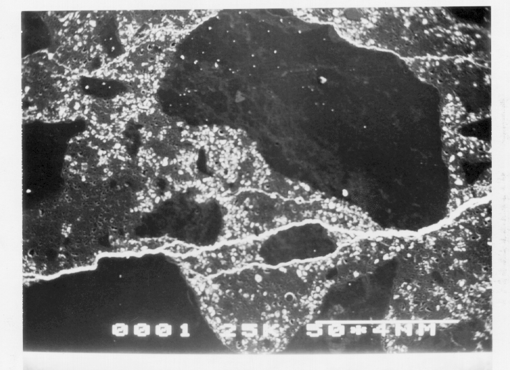
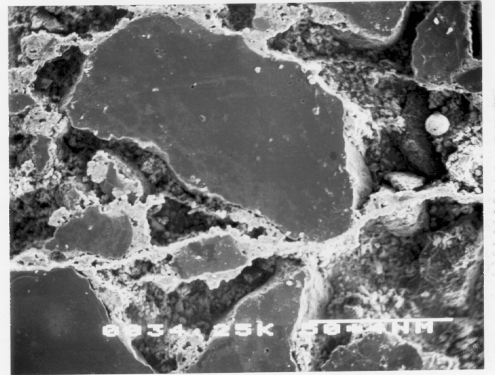
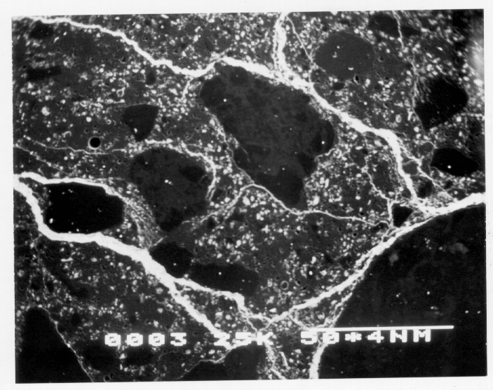
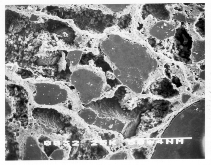
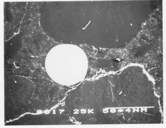
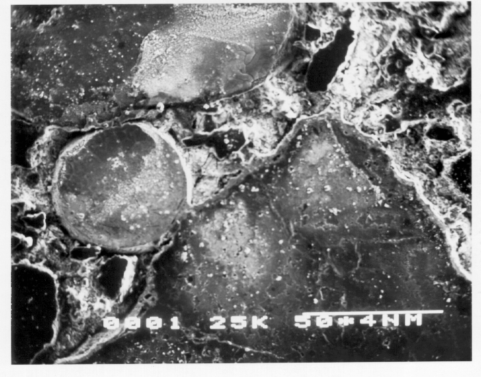
Figures 2 and 3 show micrographs of normal and high-strength concrete specimens before and after etching.
Figure 2.
Normal-strength concrete samples before (left) and after etching (right)
Figure 3.
High-strength concrete samples before (left) and after etching (right)
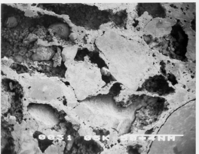
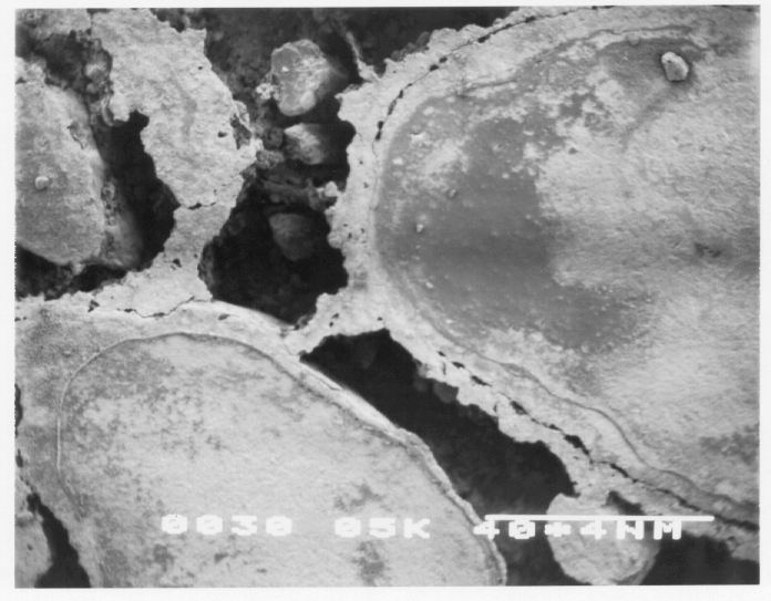
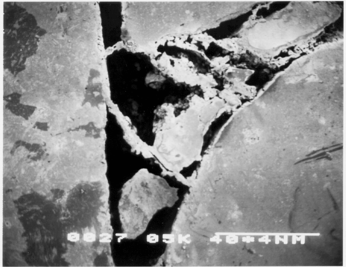
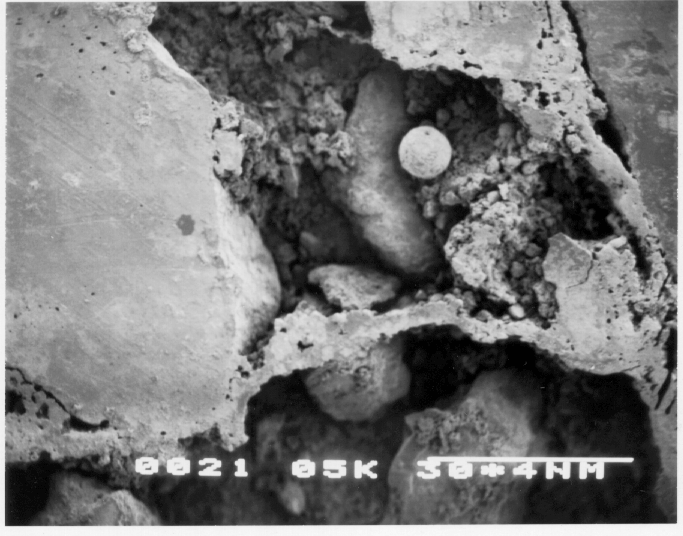
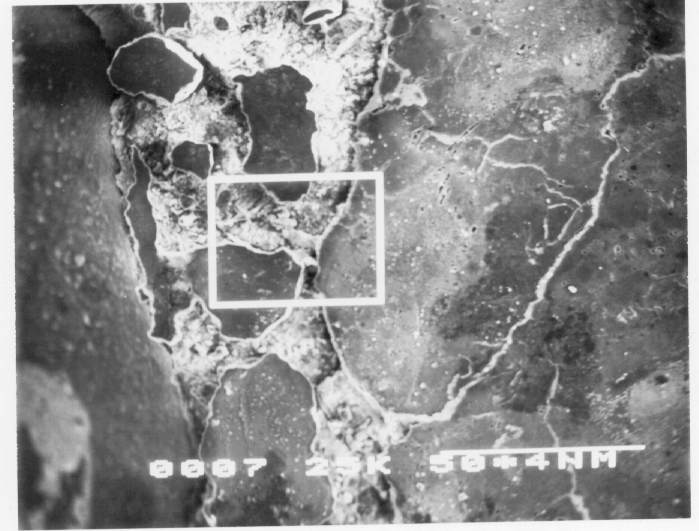
Figures 4 through 7 are micrographs obtained from SEM observations. All micrographs show great distinction between microcracks and void spaces. The cracks are mostly observed as straight surfaces and subparallel to each other, indicating crack orientation (Figure 4).
Figure 4.
Crack orientation
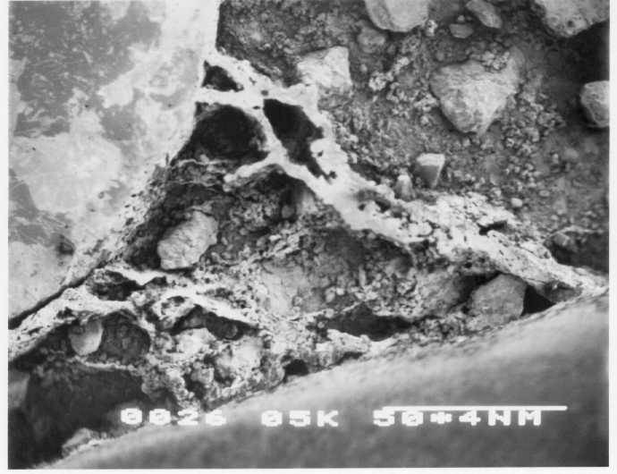
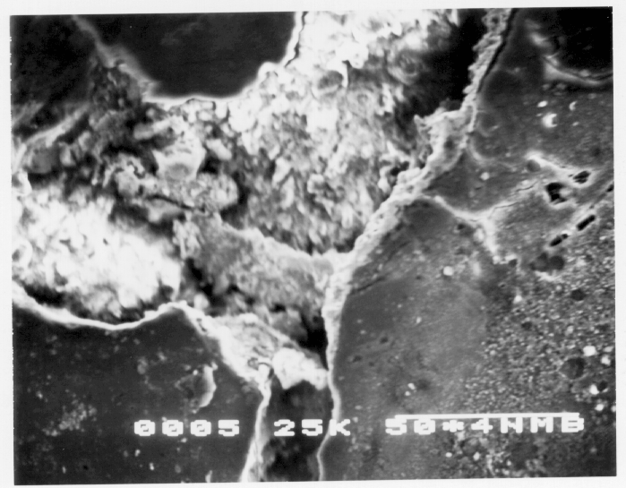
The orientation of the stress-induced microcracks were found to be within a few degrees of the direction of maximum applied stresses (8). The transition zone microcracks are curved, randomly oriented, and not straight, indicating high porosity (Figure 5). Some transition zone cracks were the result of applied stresses, but investigations have shown that very fine cracks exist in the ITZ even prior to application of the load on concrete (6). Crack initiation and propagation were the dominant mechanisms responsible for the nonlinear response of concrete subjected to uniaxial compressive loading. Cracks may have initiated in the matrix, aggregates, or in the matrix-aggregate interface.
Figure 5.
Transition zone cracks
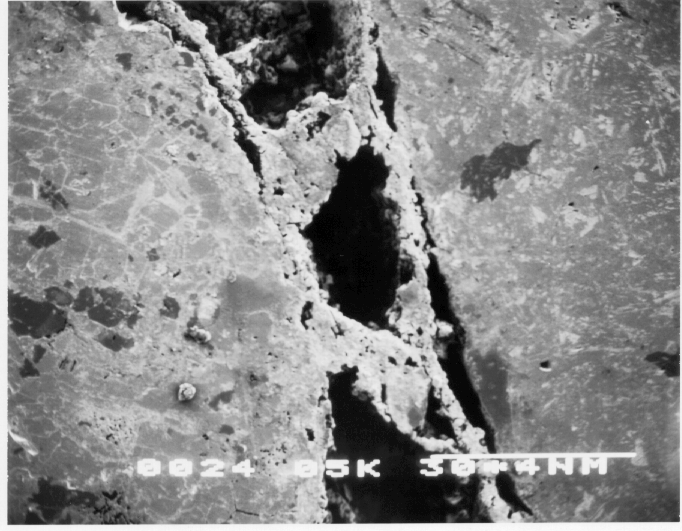
Studies conducted using microscopic analysis (6,12,13) have revealed that cracks frequently initiate at the interface and then propagate into the matrix where mortar cracks join to form a continuous crack path prior to ultimate load. Figures 4 through 7 show this phenomenon.
Figure 6.
Cracks initiating at the interface
It is noted that the cracks are of finite extent, reflecting stable growth condition. From Figure 7 it can be observed that after microcracks nucleated, they grew unstably for some distance depending on stress conditions, followed by stable growth, and finally unstable growth due to interaction of cracks.
Figure 7.
Crack growth
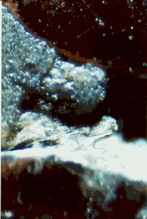
A 3D image can reveal information impossible to ascertain in a 2D image of the same specimen, i.e., details, contrast, and depth. True z-axis resolution reveals relationships not visible through conventional 2D microscopes. The ability to see in the third dimension versus the flat 2D allows one to examine thicker preparations. Stereo pair-imaging in a high-definition 3D microscope were used to observe details of topography of fracture surfaces at various degrees of magnification. Various topographic features of the fracture surfaces can be observed in three-dimensional from these images. Figure 8 shows stereo pair photographs of crack surfaces in concrete using a high-definition 3D microscope.
Figure 8.
Stereo pair photographs of crack surfaces in concrete
High-strength concrete behaves more like a homogeneous material than does normal-strength concrete. The stress-strain curves for high-strength concretes are steeper and remain closer to linearity to a higher stress-strength ratio than in normal-strength concretes. In addition, fracture in high-strength concrete tends to be characterized more accurately by linear elastic fracture mechanics than does normal-strength concrete (14). This is due to a decrease in the amount and extent of microcracking in the interfacial transition zone (ITZ) between the cement paste matrix and the aggregates. Thus the high-strength concrete exhibits a more brittle mode of fracture and less volumetric dilation (15). High-strength concrete has a stronger and tougher cement paste because of a lower water/cement ratio, which results in a closer packing of cement grains and a reduced amount of pores and cracks. Apart from this microstructurally improved matrix, high-strength concrete also has a stronger transition zone. This presumably results from the reduction of excess bleeding and the filling of gaps by mineral admixtures, which in this case was rice husk ash.
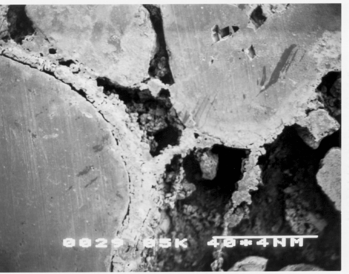
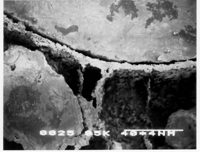
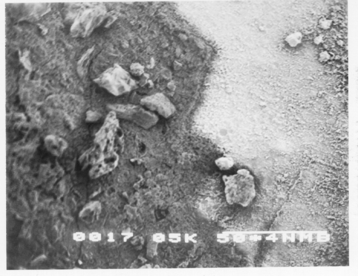
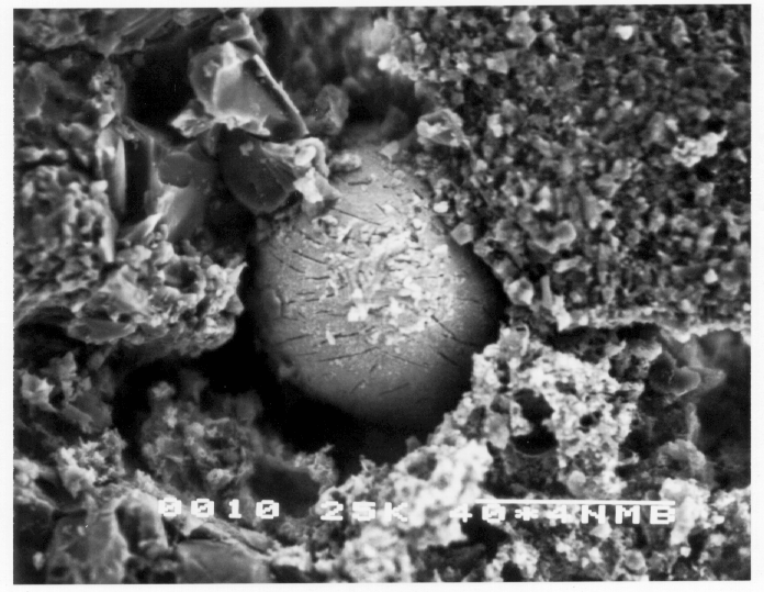
Figures 9 through 12 show two SEM micrographs from a high-strength concrete experiment. From these micrographs, it is clear that less cracking occurs in high-strength than in normal-strength concrete and because of the stronger cement paste, most of this cracking takes place in the transition zone. Figure 9 shows a SEM micrograph from the unloaded specimen of high-strength concrete. No stress-induced microcracks were observed in this section. Regions of connected porosity in the interfacial transition zone are also far less apparent because of refinement of the microstructure in this region, as can be observed in the magnified micrograph shown adjacent to it.
Figure 9.
No-load high-strength concrete
Qualitative examination of the sections indicate that the cracking was dominated by cracks at the interface between aggregate and cement paste and by the presence of regions of connected pores in the ITZ. Investigations have shown that very fine cracks at the interface between coarse aggregate and cement paste exist even prior to application of load on concrete (16). The initiation and propagation of these cracks is considered to be the dominant mechanism responsible for the nonlinear response of concrete subjected to uniaxial compressive loading.
Figure 10.
High-strength concrete
Interfacial cracks remain stable up to about 30 percent or more of the ultimate strength and then begin to increase in length, width, and number. The overall stress under which they develop is sensitive to the water/cement ratio of the paste. At 70 to 90 percent of the ultimate strength, cracks open through the cement paste and bridge the interfacial cracks and the continuous crack pattern is formed (17). Studies conducted using microscopic analysis (12,13,18) have revealed that cracks frequently initiate at the interface and then propagate into the matrix where mortar cracks join to form a continuous crack path prior to ultimate load.
Figure 11.
Pore in concrete
In the case of high-strength concrete, it is apparent that the percentage of interfacial cracks in the unloaded and uniaxially loaded specimens is much lower than in the corresponding of normal-strength concrete specimens (8). This may be partially explained by the elimination of region of connected pores which were a common feature of the ITZs of the normal-strength concrete, but also confirms the improved strength of the interfacial zone in the high-strength concrete. In the confined case the percentage of interfacial cracks is similar in the two types of concrete.
Conclusions
An experimental technique has been developed to preserve the stress-induced microcracks as they exist under load. In this technique molten Woods metal at about 96°C is used as a pore fluid at a pressure of about 10 MPa. Since Wood's metal is nonwetting, it may not penetrate to the tip of cracks, causing an additional effective compressive stress being applied at the crack tip, therefore the value of stress intensity factor is reduced compared using a wetting fluid under same stress conditions. At the stress point of interest, the temperature is reduced to solidify the metal and preserve the microstructure as it exists under load. Using low melting point metal alloy porosimetry to preserve microstructure of concrete is an effective technique. Three-dimensional observations of microstructure were made possible by dissolving concrete matrix material of the tested specimen.
Acknowledgments
The authors would like to express their appreciation to Mr. William MacCracken of the Department of Civil Engineering for his help in conducting the experiments. The study reported here was funded through the Presidential Young Investigator award from the National Science Foundation.
References
Jones, R. (1952). "A Method of Studying the Formation of Cracks in a Material Subject to Stresses," British Journal of Applied Physics, London, 229-232.
L'Hermite, R. (1954). "Present Day Ideas in Concrete Technology. Part 3: The Failure of Concrete," RILEM Bulletin, 27-38.
Hognestad, E.; Hanson, N. W.; and McHenry, D. (1955). "Concrete Stress Distribution in Ultimate Stress Design," Journal of the American Concrete Institute, Proceedings, 455-479.
Hsu, T. T. C. (1963). "Mathematical Analysis of Shrinkage Stresses in a Model of Hardened Concrete," Journal of the American Concrete Institute, Proceedings, 60(3): 371-390.
Hsu, T. T. C. and Slate, F. O. (1963). "Tensile Bond Strength Between Aggregate and Cement Paste or Mortar," Journal of the American Concrete Institute, Proceedings, 60(4): 465-486.
Hsu, T. T. C., Slate, F. O., Sturman, G. M., and Winter, G. (1963). "Microcracking of Plain Concrete and the Shape of the Stress-Strain Curve," Journal of the American Concrete Institute, Proceedings, 209-224.
Slate, F. O. and Olsefski, S. (1963). "X-Rays for Study of Internal Structure and Microcracking of Concrete," Journal of the American Concrete Institute, Proceedings, 575-588.
Nemati, K. M. (1994). "Generation and Interaction of Compressive Stress-Induced Microcracks in Concrete," Ph.D. Thesis, Department of Civil Engineering, University of California at Berkeley.
Nemati, K. M., Monteiro, P. J. M., and Cook, N. G. W. (1998). "A New Method for Studying Stress-Induced Microcracks in Concrete Using Molten Metal Alloy," American Society of Civil Engineers Materials Journal, 10(3):128-134.
Zheng, Z. (1989). "Compressive Stress-Induced Microcracks in Rocks and Applications to Seismic Anisotropy and Borehole Stability," Ph.D. Thesis, Department of Material Science and Mineral Engineering, University of California, Berkeley.
Goldstein, J. I., Newbury, D. E., Echlin, P. E., Joy, D. C., Romig, D. A., Lyman, C. E., Fiori, C., Lifshin, E. (1992). Scanning Electron Microscopy and X-Ray Microanalysis, Plenum Press, New York.
Shah, S. P. and Chandra, S. (1970). "Fracture of Concrete Subjected to Cyclic and Sustained Loading, " ACI Journal, Proceedings, 67(10): 816-825.
Shah, S. P. and Sankar, R. (1987). "Internal Cracking and Strain Softening Response of Concrete under Uniaxial Compression," ACI Materials Journal, 84(3): 200.
Gettu, R., Bazant, Z. P., and Karr, M. E. (1990). "Fracture Properties and Brittleness of High Strength Concrete," ACI Journal of Materials.
Carrasquillo, R. L., Nilson, A. H., and Slate, F. O. (1981). "Properties of High Strength Concrete Subject to Short-Term Loads," ACI Journal, 171-178.
Hsu, T. T. C., Slate, F. O., Sturman, G. M., and Winter, G. (1963). "Microcracking of Plain Concrete and the Shape of the Stress-Strain Curve," Journal of the American Concrete Institute, Proceedings, 209-224.
Neville, A. M. (1996). Properties of Concrete, John Wiley & Sons, Inc., New York.
Suarez-Rivera, F.R., Cook, P.J., Cook, N.G.W., and Myer L.R. (1991), "The Role of Wetting Fluids during Indentation of Porous Rocks", in Rock Mechanics as a Multidisciplinary Science, Proceedings of the 32nd US Rock Mechanics Symposium, JC Rolgiers, (ed.) Balkema, The Netherlands, 683-692.


